• Skip to primary navigation
  • Skip to main content
PMT Security Logo

PMT Security

Advanced Access Control

  • Home
  • About Us
    • Security and Trust
    • Our Partners
    • Our Integrators
  • Solutions
    • Education
    • Retirement & Healthcare
    • Manufacturing
    • Government Facilities
    • Residential
    • Retail Businesses
    • Campgrounds & Outdoor Resorts
  • Products
    • Access Control
      • Control Features
      • Reporting & Monitoring
      • Control Module
      • Digital IO Module
      • Reader Module
      • Readers
    • Video Management
      • Integration
      • Analytics
      • Search & Export
    • Visitor Management
    • Intercom
    • Live Guard Video Monitoring
    • Housings & Pedestals
  • Support
    • Knowledgebase
    • Download Center
    • License Request
    • RMA Request Form
  • Blog
  • Contact Us

PMT Security Hardware

Setting I/O up with Request to Exit and Door timers 

Setting I/O up with Request to Exit and Door timers 

How to use Input/Output Hardware for Request to Exit and Door Open Sensor Timers

Setting I/O up with Request to Exit and Door timers 

First, we need to set up your REQUEST TO ENTER/EXIT (RTE) input on the I/O module. 

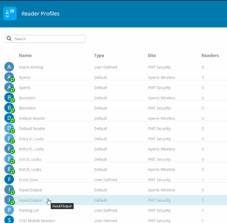
  1. Go to SETUP \ READER PROFILES: 
  1. Select the READER PROFILE that your I/O module resides in: 
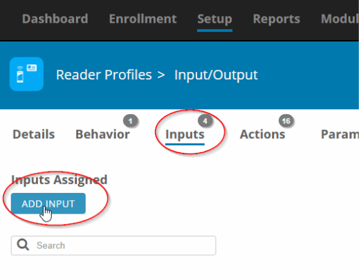
  1. Go to INPUTS and click ADD INPUT: 
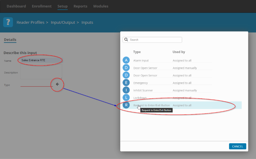
  1. Give the input a descriptive name and then click on the arrow at the bottom in order to select the type of input that you want to set up, in this case we will select REQUEST TO ENTER/EXIT BUTTON-ASSIGNED TO ALL: 
  1. Select the associated input, in this case we will use input 7 to connect our RTE button to the I/O Mdule. 
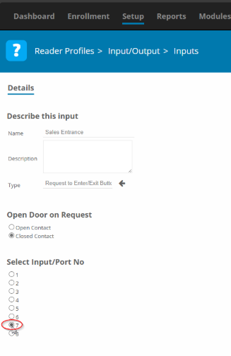
Save. 

You can now see your Request to exit listed under Inputs: 

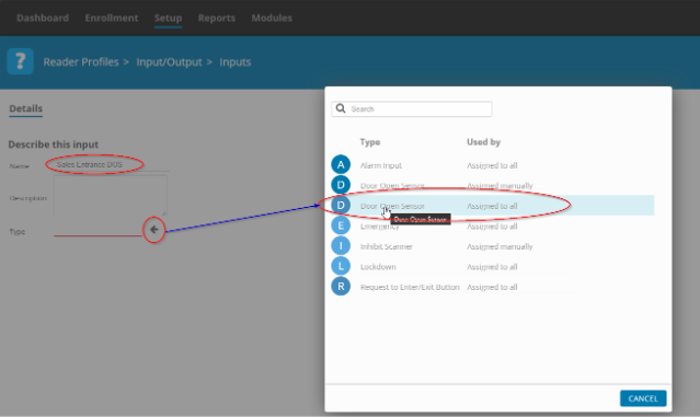
  1. Now, add your door sensor with the same procedure, but instead of ‘Request to Exit’ Select ‘Door Open Sensor – Assigned to all’ 
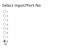
  1. Select the input that is going to have the door sensor connected to it: 

Remember to save: 

You can now see your door sensor listed under Inputs 

  1. Go to SETUP \ READERS 

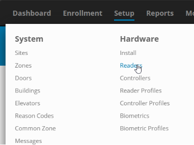
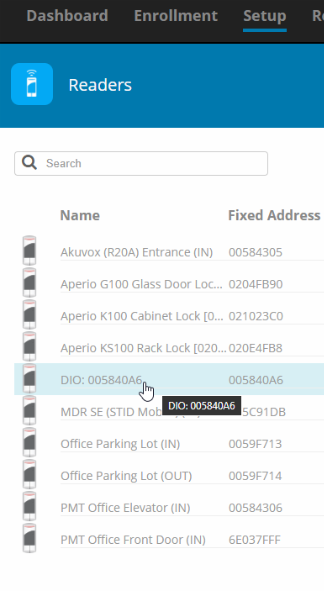
Find your I/O module in the list and click on it: 

We are now going to associate the REQUEST TO ENTER/EXIT with a DOOR TIMER. 
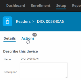
  1. Go to ACTIONS 
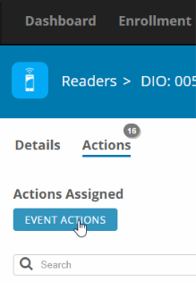
  1. Click on EVENT ACTIONS: 
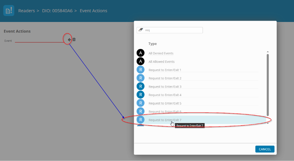
  1. In the new view, click on the arrow and then in the pop-up, select the RTE input that you previously set up. In this example we used INPUT 7 when we set up the RTE. 
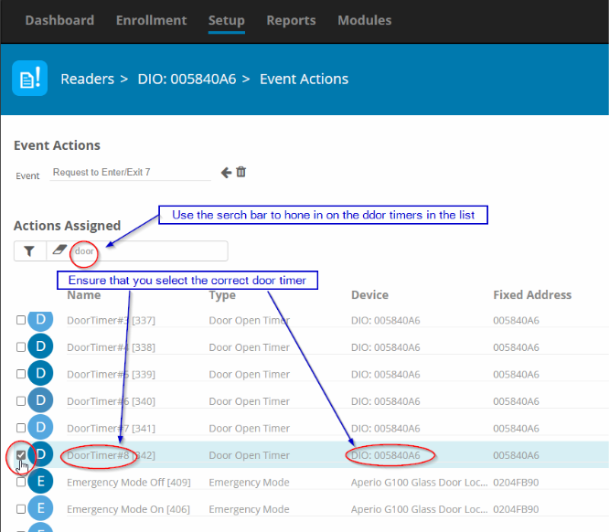
  1. In the new view, find the DOOR TIMER that we want to associate with the REQUEST TO ENTER/EXIT that we previously set up. Because the list can be long, it is advised that you use the search bar to narrow the view: 
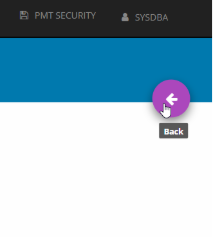
Click BACK to save: 

You have now successfully set up a RTE and associated it with a DOOR TIMER. 

Need further assistance?

Submit a Support Ticket

Submit a Support Ticket

FAQ

General

Technical Bulletins

Access Control

AmanoNet

Nexxus220

Omnia

Omnia Lite

PM Tronics Hardware

Amano Readers and Credentials

Legacy Hardware

Partner Products

Partner Products

Video Management Systems

Cathexis Video (Amano Vision)

AmanoDVMS

Vision

Setting Read Range on a Conekt Reader

Setting Read Range on a Conekt Reader

This document explains how to set the read range on a Conekt Reader.

Applies to: CSR-35 

Toggle between CSR-35P (presentation) and CSR-35L (long range) reader modes

1. Cycle power on the reader

Note:

  • There is a 10-minute window for configuration.
  • After 10-minutes the reader won’t accept configuration cards.
  • Cycle power again for an additional 10-minute window.

2. Present BLE_Mode control card

Note:

  • 1-beep indicates reader was set as a CSR-35P reader (presentation mode)
  • 2-beeps indicate reader was set as a CSR-35L reader (long range mode)
  • Readers can be toggled back and forth between the two configurations

Read range settings for CSR-35L (long range mode) reader

1. Configure reader to the CSR-35L long range mode

Note:

  • Not applicable when reader is in the CSR-35P (presentation) configuration

2. Present the BLE_Range_Setting control card as many times as necessary to select the read range option desired; setting indicated by the number of beeps outputted by the reader.

Read Range Options:

  • Short: 1-beep = up to 12-inches
  • Medium: 2-beeps = up to 7-feet
  • Long: 3-beeps = up to 15-feet
  • Max: 4-beeps = up to 50-feet

Please note that all mobile devices are designed differently, and read ranges may vary due to component differences, BLE signal strength, phone cases, amongst other factors. Please contact Farpointe’s Customer Support team if you have any questions.

Need further assistance?

Submit a Support Ticket

Submit a Support Ticket

FAQ

General

Technical Bulletins

Access Control

AmanoNet

Nexxus220

Omnia

Omnia Lite

PM Tronics Hardware

Amano Readers and Credentials

Legacy Hardware

Partner Products

Partner Products

Video Management Systems

Cathexis Video (Amano Vision)

AmanoDVMS

Vision

Change Modulation mode on XQT904 Quad Transmitter

Change Modulation mode on XQT904 Quad Transmitter

When using the XQT904 transmitter with an Amano UHF Receiver (HRR900), you need to make sure the transmitters are set to FSK mode.  Follow the procedure below to change modulation modes.

Procedure to Change Modulation Modes

  1. Press and hold down Buttons 1 and 4 at the same time until the LED begins to flash slowly.
  2. Within three seconds, press Button 3 to change the Modulation Mode
  3. On pressing Button 3, the LED indicates the new Modulation Mode selection:
    • Continuous red LED indicates Quad Transmitter is now OOK Mode
    • Fast flashing red LED indicates the Quad Transmitter is now in FSK Mode
  4. After indicating the new Modulation Mode for two seconds, the LED turns off and the Quad Transmitter is ready for use.

Need further assistance?

Submit a Support Ticket

Submit a Support Ticket

FAQ

General

Technical Bulletins

Access Control

AmanoNet

Nexxus220

Omnia

Omnia Lite

PM Tronics Hardware

Amano Readers and Credentials

Legacy Hardware

Partner Products

Partner Products

Video Management Systems

Cathexis Video (Amano Vision)

AmanoDVMS

Vision

  • Facebook
  • LinkedIn
  • Twitter

PMT Security

Copyright © 2026 PMT Security, Inc. | All Rights Reserved

  • Privacy Policy
  • Terms of Use
  • Cookie Policy
  • Accessibility
  • Contact Us