• Skip to primary navigation
  • Skip to main content
PMT Security Logo

PMT Security

Advanced Access Control

  • Home
  • About Us
    • Our Partners
    • Our Integrators
  • Solutions
    • Education
    • Retirement & Healthcare
    • Manufacturing
    • Government Facilities
    • Residential
    • Retail Businesses
    • Campgrounds & Outdoor Resorts
  • Products
    • Access Control
      • Control Features
      • Reporting & Monitoring
      • Control Module
      • Digital IO Module
      • Reader Module
      • Readers
    • Video Management
      • Integration
      • Analytics
      • Search & Export
    • Visitor Management
    • Intercom
    • Live Guard Video Monitoring
    • Housings & Pedestals
  • Support
    • Knowledgebase
    • Download Center
    • License Request
    • RMA Request Form
  • Blog
  • Contact Us

Security Best Practices & Support

Deleting Tag Holders in OMNIA

Deleting Tag Holders in OMNIA

How to Delete Tagholders in OMNIA

NOTE: only the Operator Login of sysdba has the abiltity to delete tagholders. Operator Login’s with the Administrator Operator Profile will not have the abilty to delete tagholders.

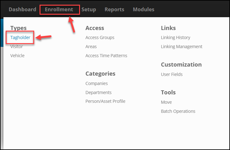
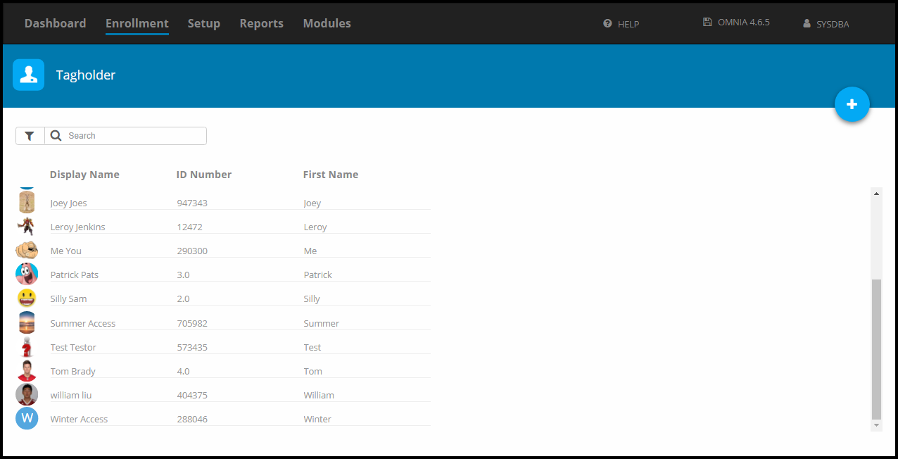
In the OMNIA URL, Go to Enrollment, then select Tagholders.

Open OMNIA URL, Select  "Enrollment" from Navigation, then Select "Tagholder" located under the heading "Types"

Scroll down to the Tagholder to delete, hover over the Tagholder and select the Delete Button.

Scroll down to locate Tagholder to delete, hover over the Tagholder and select the Delete trashcan icon.

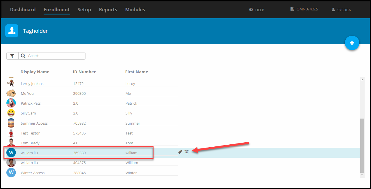
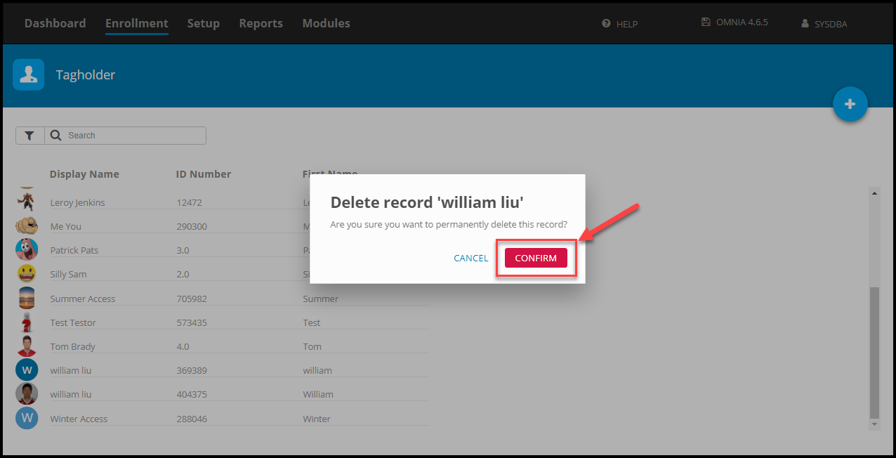
Select Confirm to complete the deletion

Select "Confirm" to complete the deletion.
Tagholder no longer listed. Repeat steps to delete another tagholder.

Repeat as necessary.

Need further assistance?

Submit a Support Ticket

Submit a Support Ticket

FAQ

General

Technical Bulletins

Access Control

AmanoNet

Nexxus220

Omnia

Omnia Lite

PM Tronics Hardware

Amano Readers and Credentials

Legacy Hardware

Partner Products

Partner Products

Video Management Systems

Cathexis Video (Amano Vision)

AmanoDVMS

Vision

Unlock on First Tag in AmanoNet

Setting up Unlock on First Tag in AmanoNet

Steps and Procedure to Configure a Valid Tag to Open and Keep a door unlocked for a specific amount of time in AmanoNet.

Unlock on First Tag feature in AmanoNet provides the facility of unlocking selected door(s) when the first valid Tag is presented during a specified time period. The door remains unlocked for that time period, but is locked outside that time period, opening only on presentation of a valid Tag.


Example
In the following example procedure, activate the Unlock on First Tag feature only on weekdays from 7 am to 5 pm. This means that you must create the following Device Time Patterns (in Access) for the Terminal(s) concerned:

  • A Device Time Pattern from 7 am until 5 pm on weekdays (Monday to Friday). This is the period for which the Unlock on First Tag feature must be enabled.
  • A Device Time Pattern from Sunday until Friday, 5 pm until 12 am. This is the remaining time on each of the above days during which the Unlock on First Tag feature must be disabled.
  • A Device Time Pattern from Sunday until Friday, 12 am until 7 am. The Sunday period covers the time from midnight to 7 am on Monday.
  • A Device Time Pattern called Deactivate Relay at 17:00. Set the start time to 5 pm and select Monday to Friday. This will End the Unlock on First Tag
  • A Device Time Pattern for Saturday, Sunday and public holidays for the full 24 hours. These are the days on which the Unlock on First Tag feature must be disabled.


Device Time Pattern Setup


1. In Access, in the Navigate Pane (from the Hierarchical Tree) select Device Time Patterns

2. In the Main Pane, click the Plus button.

In AmanoNet select "Device Time Patterns" from system menu located to the left. Then select the "+" symbol at the bottom of the window.

3. In the Description textbox, enter a name for the Device Time Pattern.

4. If required, complete the Start Date and Stop Date textboxes.

5. In the Start Time field, enter 0700.

6. In the Duration field, enter 1000.

7. Select the Monday through Friday checkboxes.

Set-up your time pattern.
Describe the pattern, set your dates and time durations, and select the days of the week required for this device time pattern.

8. Repeat the processes mentioned in steps 2 to 7 for the remaining Device Time Patterns. When are complete it should look similar to Below.

Follow steps 2 -7 for your remaining device time patterns, when you are finished your device time patterns will be displayed accordingly in AmanoNet.

Relay Action Setup

NOTE: This Action enables the relay for an indefinite period.

Create New Action – Mon-Fri 07:00-17:00 Device Time Pattern


1. Select the Actions tab, for the output relay on the Terminal controlling the door strike.

2. In the Main Pane, click the Plus Button.

3. In the Action Name textbox, assign your action the name Enable Relay Indefinitely.

4. Alongside the Time Pattern textbox, click the browse button.

5. From the list of displayed Device Time Patterns, select the Mon-Fri 07:00-17:00 record.

6. Click the button Save Button.

7. At the New Action dialog, click the save button.

8. In the Action Parameters dialog, set the Duration (0.1s) to 65535.

9. Click the Save Button.

Create New Action - Mon-Fri 07:00-17:00 Device Time Pattern.

Select the Actions tab, for the output relay on the Terminal controlling the door strike. Select the "+" symbol.
Displays how to Enable Relay in AmanoNet.
To activate indefinitely in AmanoNet set duration to 65535

Create New Action – Sat, Sun, Hol 24hrs Device Time Pattern


1. In the Main Pane, click the Plus Button.

2. In the Action Name textbox, assign the action a name (for example Drive Relay 4 Seconds).

3. Alongside the Time Pattern textbox, click the browse button.

4. From the list of displayed Device Time Patterns, select the Sat, Sun, Hol 24 Hrs record.

5. Click the Save Button.

6. At the New Action dialog, click the Save Button

7. In the Action Parameters dialog, set the Duration (0.1s) to 40 (4 seconds).

8. At the Action Parameters dialog, click the Save Button.

Create New Action - Sat, Sun, Hol 24hrs Device Time Pattern
Sat, Sun, Hol 24hrs Device Time Pattern duration 40


Edit Action – Sun-Fri 17:00-00:00 Device Time Pattern


1. In the Main Pane select the existing Relay – Allowed In Action.

2. Click the Gear button.

3. In the Action Name textbox, assign the action a new name (for example Sun-Fri 1700-0000).

4. Alongside the Time Pattern textbox, click the browse button.

5. From the list of displayed Device Time Patterns, select the Sun-Fri 17:00-00:00 record.

6. Click the Save Button.

7. At the Edit Action dialog, click the Save Button

Create New Action – Sun-Fri 00:00-07:00 Device Time Pattern


1. In the Main Pane, click the Plus Button.

2. In the Action Name textbox, assign your action a name (for example Sun-Fri 0000-0700).

3. Alongside the Time Pattern textbox, click the browse button.

4. From the list of displayed Device Time Patterns, select the Sun-Fri 00:00-07:00 record.

5. Click the Save Button.

6. At the New Action dialog, click the Save Button.

7. At the Action Parameters dialog, click the Save Button.

Create New Action – Deactivate Relay at 17:00 Device Time Pattern


1. In the Main Pane, click the Plus Button.

2. In the Action Name textbox, assign your action a name (for example Deactivate Relay).

3. Alongside the Time Pattern textbox, click the browse button.

4. From the list of displayed Device Time Patterns, select the Deactivate Relay at 17:00 record.

5. Click the Save Button.

6. At the New Action dialog, click the Save Button.

7. In the Action Parameters dialog, set the Duration (0.1s) to 65535.

8. At the Action Parameters dialog, click the Save button.

Create New Action - Deactivate Relay at 17:00 Device Time Pattern
To deactivate indefinitely set duration to 65535

AmanoNet New Action – All Relays


1. In the Main Pane, click the Plus Button.

2. From the Select Action Type drop-down list, select the Multiple Actions option.

3. In the Action Name textbox, assign your action a name (for example All Relays).

4. Click the Save Button

5. In the Action Parameter dialog, for the First Action, click the 1 button.

6. From the list of displayed actions, select the Sun-Fri 1700-0000 action created earlier.

7. For the Second Action, click the 2 button.

8. From the list of displayed actions, select the Sun-Fri 0000-0700 action created earlier.

9. For the Third Action, click the 3 button.

10. From the list of displayed actions, select the Enable Relay Indefinitely action created earlier.

11. For the Fourth Action, click the 4 button.

12. From the list of displayed actions, select the Drive Relay 4 Seconds action created earlier.

13. Click the Save button.

14. At the Action Parameters dialog, click the Save button.

NOTE: Steps 5 through 12 are shown all at once for clarity. The Action Selector window will close and open between each step after selecting the Save Button (13)

AmanoNet Active System Events Edit

1. In the Main Pane, click the Active System Events button.

On opening, under Actions for Allowed Events, the First Action appears as Sun-Fri 1700-0000,

add the remaining actions as follows:


2. Under Actions For Allowed Events, replace the First Action, by clicking the 1 button.

3. From the list of actions displayed, select the All Relays action you created earlier.

4. Click the Save Button.

5. At the Active System Events Editor dialog, click the Save Button.

6. At the Confirm Save dialog, click the Yes button.

AmanoNet Time Triggered Action Setup

1. In Access, in the Navigate Pane (from the Hierarchical Tree), select Time Triggered Actions.

2. In the Main Pane, click the Plus Button.

3. In the Action Name textbox, give your Time Triggered Action a meaningful name (for example

Deactivate Relay 1).

4. Click the Trigger Time’s associated browse button.

5. From the list of displayed Device Time Patterns, select the Deactivate Relay at 17:00 record.

6. Click the Save Button.

7. Click the Execute Action’s associated browse button.

8. From the list of displayed actions, select the Deactivate Relay action created earlier.

9. Click the Save Button.

10. At the Create Time Triggered Action dialog, click the Save Button

Need further assistance?

Submit a Support Ticket

Submit a Support Ticket

FAQ

General

Technical Bulletins

Access Control

AmanoNet

Nexxus220

Omnia

Omnia Lite

PM Tronics Hardware

Amano Readers and Credentials

Legacy Hardware

Partner Products

Partner Products

Video Management Systems

Cathexis Video (Amano Vision)

AmanoDVMS

Vision

Database Migration from Nexus220/IXP220 to OMNIA

What Data is Migrated from Nexus220 during a Database Conversion?

PMT Security offers a conversion service to migrate data from an Nexus220 system to an OMNIA system. It is however a limited migration and only select data is migrated.

Database migration from Nexus220/IXP220 to OMNIA

The following data IS migrated from the IXP220 database:

  • Limited master data (first name, last name, ID number, company)
  • Tagholder images
  • Departments and department assignments
  • Tags
  • Access groups and access group assignments
  • Access time patterns and assignments
  • Biometric templates (fingerprints)

The following data IS NOT migrated from the IXP220 database:

  • Hardware (controllers, terminals, readers, including 3rd party biometric readers)
  • Doors
  • Areas
  • Transactions
  • Operators
  • Other miscellaneous settings not mentioned in the list of migrated data

If there is a need to refer to transactions from the Nexus220 system for historical purposes, it is recommended that this is done via Nexus220 reports from the old Nexus220 database.


Hardware must be installed again the new system, doors created and assigned to areas. Areas can be linked to the migrated access groups to restore correct access assignments to tagholders.


IXP220 system controllers are not compatible with OMNIA, and must be replaced with the appropriate controller for the new system.

Need further assistance?

Submit a Support Ticket

Submit a Support Ticket

FAQ

General

Technical Bulletins

Access Control

AmanoNet

Nexxus220

Omnia

Omnia Lite

PM Tronics Hardware

Amano Readers and Credentials

Legacy Hardware

Partner Products

Partner Products

Video Management Systems

Cathexis Video (Amano Vision)

AmanoDVMS

Vision

Convert a Nexus Lite Database into OMNIA Lite Database

Convert a Nexus Lite Database into OMNIA Lite Database

How to guide to convert a Nexus Lite Access Control System into an OMNIA Lite Access Control System.

Download the OMNIA Firmware Upgrade Utility below:

OMNIA Firmware Upgrade Utility

After Downloading the OMNA Firmware Upgrade Utility, Run the installer as Administrator.

Select "Run As Administrator" from menu.

Select the installation Language.

Choose your installation language from pop up wizard.

Accept the License Agreement and Click Next.

Select "I accept  the agreement" from License Agreement Terms from OMNIA Firmware Upgrade Utility Wizard Notification, then Click "Next".

You may select create a desktop Shortcut, Click Next

Select "Create a desktop shortcut" in prompt window, and Click "Next >"”/></figure>


<p>Click Finish to complete the installation</p>


<figure class=Completing the OMNIA Firmware Upgrade Setup Wizard prompt, click, "Finish"

This will install OMNIA Firmware Upgrade Utility Folder on the C: Drive

OMNIA Firmware Upgrade Utility Folder on the C: Drive

Inside the OMNIA Firmware Upgrade Utility Folder, Select OMNIA Firmware Upgrade Utility.exe

OMNIA Firmware Upgrade Utility Folder, Select OMNIA Firmware Upgrade Utility.exe (Application)

When the OMNIA Firmware Upgrade Utility opens, use the search function to find the Nexus Lite Controller.

OMNIA Firmware Upgrade Utility will open, use the search function to find the Nexus Lite Controller: Click "Search for Devices"

The OMNIA Firmware Upgrade Utility will search the local network and find the Nexus Lite Controller.

Results from local network will be display Nexus Lite files

Click on the Nexus Lite Controller, Select the Backup tab, Then Select Backup

Select Nexus Lite Controller from search results, Select the Backup tab, Then Click Backup

Choose the location of the Nexus Lite Backup, by default the OMNIA Firmware Upgrade Utility will place the back up in the OMNIA Firmware Upgrade Utility Folder. Click Open.

Choose the location of the Nexus Lite Backup, by default the OMNIA Firmware Upgrade Utility will place the back up in the OMNIA Firmware Upgrade Utility Folder. Click Open.

The Backup Process will begin and will display a message when completed. Click OK

The Backup Process will begin and will display a message when completed. Click OK on Backup Completed Message.

Unless you chose a different path in one of the previous steps, the back up will be placed inside the OMNIA Firmware Upgrade Utility Folder.

Locate backup file in the OMNIA Firmware Upgrade Utility Folder. (BAK File)

Remove the Ethernet Cable from the Nexus Lite Controller and connect it to the OMNIA Lite Controller. The APC controller will need to have the Dips Set to 0100 ( 1 off, 2 on, 3 off, and 4 off).

If there were any iTRT’s connected via RS485, move the RS485 connection to the OMNIA Lite Controller. 

NOTE: You will have to change the A and B wires as the 485 Bus connection is different on the                   OMNIA Lite Controller

Use the OMNIA Firmware Upgrade Utility to find the OMNIA Lite Controller.

Use the OMNIA Firmware Upgrade Utility to find the OMNIA Lite Controller.

When the OMNIA lite controller is found, Click on the controller, Click on the Backup Tab, Then click restore.

When the OMNIA lite controller is found, Click on the controller, Click on the Backup Tab, Then click restore.

Select the Location of the Nexus Lite Backup, Click Open

Select the Location of the Nexus Lite Backup, Click Open

The backup will begin. You will receive a Device Discovery Failed message. This is normal because the Backup is changing the IP address of the OMNIA Lite Controller to the previous IP Address of the Nexus Lite Controller and the OMNIA Firmware Upgrade Utility is not finding it at the old IP address.

Device Discovery Failed message is normal, Select "Okay"

In the lower left of your PC you will received a message that the restore is complete.

Java (TM) Platform SE binary, Firmware Upgrade Utility Restore Done System Notification

When you use the OMNIA Lite Firmware Upgrade Utility, you will find the OMNIA Lite Controller. Notice the Controller’s name changed from OMNIA Lite to Nexus Lite, the MAC address is the MAC of the OMNIA Lite Controller, and the IP address is the IP address of the Nexus Lite Controller.

NOTE:  The Nexus Lite name change is due to the Backup and does not affect the OMNIA Lite Controller.

NOTE:  The Nexus Lite name change is due to the Backup and does not affect the OMNIA Lite Controller.

After the backup is complete, you will need to log into OMNIA lite, update the time, run discovery and swap the reader terminals from NexusLite Board Fixed Addresses to the Wiegand Reader Modules Fixed Addresses.

Need further assistance?

Submit a Support Ticket

Submit a Support Ticket

FAQ

General

Technical Bulletins

Access Control

AmanoNet

Nexxus220

Omnia

Omnia Lite

PM Tronics Hardware

Amano Readers and Credentials

Legacy Hardware

Partner Products

Partner Products

Video Management Systems

Cathexis Video (Amano Vision)

AmanoDVMS

Vision

Creating an Input on a Wiegand Reader Module to Generate a Lockdown/Emergency Mode For a Single APC Controller In OMNIA

Creating an Input on a Wiegand Reader Module to Generate a Lockdown/Emergency Mode For a Single APC Controller In OMNIA

How to create an input that will put the single APC Controller into Lockdown or Emergency Mode in OMNIA

Emergency
Emergency inputs are associated with fire alarms (3rd Party System Activation) or emergency call points (Manual Activation).
Activating this input will raise an Emergency event that will unlock all your
emergency doors.
In the following example, we will use the DOS (Input 1) input on a Wiegand Reader Module to activate Emergency.

Input Emergency Mode Off
Input Emergency Mode On 
Wiegand Reader Module (Input 1)

REMEMBER: DOS is always input 1 and RTE is always input 2

Lockdown 

Lockdown inputs are associated with Intruder/Active Shooter emergency call points.

Activating this input will raise a Lockdown event that will prevent the unlocking of your emergency doors.

In the following example, we will use the RTE (Input 2) input on a Wiegand Reader Module to activate Lockdown,

Input Lockdown Mode Off
Input Lockdown Mode On
Wiegand Reader Module (Input 2)

REMEMBER:  DOS is always input 1 and RTE is always input 2.

Location of Input 1 (DOS) and Input 2 (RTE) on Wiegand Reader Module for OMNIA

Note
This method will only affect the doors connected to the same system controller
as this Wiegand Reader Module. To activate Emergency mode across multiple controllers, see Configuring Emergency Input Across Multiple Controllers

Configuring an Emergency Input

These steps apply to any reader in any profile

  1. Open the Reader Profile ( Ensure this contains the correct reader being used for the input ) or Create a New Reader Profile ( Ensure you select the correct Reader being used for the input ) For This Scenario , a new Reader Profile was created. Reader Profile named Lockdown/Emergency. For Simplicity we have used the same Wiegand Reader Modules inputs for both Lockdown (Input 2)  and Emergency (Input 1). The Wiegand Reader Modules Fixed Address is 005DC20.
  2. Select Inputs then select Add Input
  3. Name the input.
  4. Select the type of input, for this case Emergency or Lockdown
  5. Select the Contact State and Input Number
  6. Save

1.  Open the Reader Profile

Located under Set-Up - Open Reader Profiles > Lockdown / Emergency, Select Readers Tab

Select the Reader the Inputs are associated with.

Select the Reader the Inputs are associated. Eg. Quick Door 3 (IN)

2. Select Inputs then select Add Inputs.

Select Inputs Tab, then Select "ADD INPUT"

3. Name the input.

4. Select the type of input, Lockdown or Emergency

Select the "type" of input, Lockdown or Emergency.

5. Select the Contact State and Input Number

REMEMBER:  DOS is always input 1 and RTE is always input 2.

Lockdown

Lockdown
Select the Contact State and Input Number

REMEMBER:  DOS is always input 1 and RTE is always input 2.

Emergency

Emergency
Select the Contact State and Input Number

REMEMBER:  DOS is always input 1 and RTE is always input 2.

Emergency and Lockdown Behavior
After creating an emergency or lockdown input, you need to decide how all your readers
will behave during Emergency Mode and Lockdown Mode.

Emergency Mode

By default, your readers will flash green but no relays will drive. The state of the relays will need to be changed.

Lockdown Mode

By default,  your readers will flash red and no relays will drive


To configure the Modes: go to, Setup>Hardware>Reader Profiles> select profile >Behavior


Steps:
1. Select the Reader Profile for the readers you wish to unlock/lockdown
2. Select the Behavior then Edit Behavior

3. Search for Emergency/Lockdown
4. Select Output States
5. Select Relay Contact State then for Emergency Mode select Drive relay in this mode, for Lockdown leave section at Do Not Drive Relay

Under Setup Tab, Select Reader Profiles > Default Reader

Select Behaviour Tab
Click "EDIT BEHAVIOR"
Select E (Emergency) or L (Lockdown)

Emergency

Emergency Relay Contact State
Drive relay in this mode

Lockdown

Lockdown Relay Contact State
Do NOT drive relay in this mode

Now all the readers in the selected Reader Profile will drive their relays during
Emergency Mode and will not drive relays in Lockdown Mode. Repeat these steps for any other required Reader Profiles.

Need further assistance?

Submit a Support Ticket

Submit a Support Ticket

FAQ

General

Technical Bulletins

Access Control

AmanoNet

Nexxus220

Omnia

Omnia Lite

PM Tronics Hardware

Amano Readers and Credentials

Legacy Hardware

Partner Products

Partner Products

Video Management Systems

Cathexis Video (Amano Vision)

AmanoDVMS

Vision

  • « Go to Previous Page
  • Page 1
  • Interim pages omitted …
  • Page 6
  • Page 7
  • Page 8
  • Page 9
  • Page 10
  • Interim pages omitted …
  • Page 23
  • Go to Next Page »
  • Facebook
  • LinkedIn
  • Twitter

PMT Security

Copyright © 2026 PMT Security, Inc. | All Rights Reserved